Hello Sphere Ray Tracing
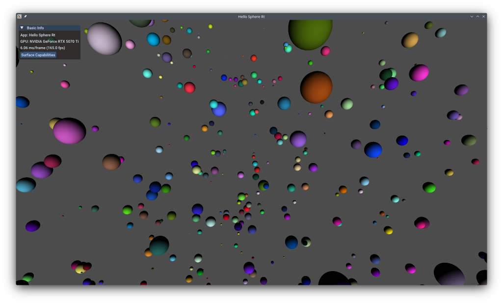
This example shows advanced ray tracing with custom intersection shaders that define ray-primitive intersection tests in shader code. Unlike Hello Triangle Ray Tracing which uses built-in triangle intersection, this example traces rays against axis-aligned bounding boxes (AABBs) and performs sphere-ray intersection analytically in an intersection shader. This technique enables ray tracing of procedural geometry like spheres, tori, fractals, and implicit surfaces without storing triangle meshes.
The example does not use the KDGpuExample helper API, demonstrating low-level ray tracing setup.
Overview
What this example demonstrates:
- Creating acceleration structures with AABB primitives
- Custom intersection shaders for procedural geometry
- Analytic sphere-ray intersection (quadratic equation solving)
- Ray tracing pipeline with procedural hit groups
- Shader binding table (SBT) for custom intersections
Use cases:
- Procedural geometry (spheres, ellipsoids, tori)
- Implicit surfaces (metaballs, signed distance functions)
- Volume rendering (clouds, smoke, fog)
- Fractals and mathematical shapes
- Mixed procedural/triangle rendering
Vulkan Requirements
- Vulkan Version: 1.2+
- Extensions:
- VK_KHR_ray_tracing_pipeline
- VK_KHR_acceleration_structure
- VK_KHR_buffer_device_address
- Features:
rayTracingPipelineaccelerationStructurebufferDeviceAddress
- Shader: SPIR-V 1.4+ with ray tracing and intersection shader support
Key Concepts
Custom Intersection Shaders:
Built-in triangle intersection is fast but limited. Intersection shaders let you define custom ray-primitive tests in shader code. When a ray hits an AABB, the intersection shader is invoked to perform precise intersection testing.
Spec: https://registry.khronos.org/vulkan/specs/1.3-extensions/man/html/VK_KHR_ray_tracing_pipeline.html
AABB Geometry:
Procedural primitives use AABBs (axis-aligned bounding boxes) instead of triangles. The AABB is a conservative bound - ray traversal tests ray-AABB intersection first (fast), then invokes the intersection shader only if the ray hits the AABB.
For spheres:
| AABB sphereAABB = {
.min = center - vec3(radius),
.max = center + vec3(radius)
};
|
Procedural Hit Groups:
Ray tracing shader groups for procedural geometry use RayTracingShaderGroupType::ProceduralHit which contains an intersection shader plus closest-hit shader (and optional any-hit).
Implementation
Ray Tracing Pipeline
First, we need to create a ray tracing pipeline. Unlike graphics pipelines, ray tracing pipelines can contain multiple shader stages for different purposes: ray generation, miss, closest hit, and intersection.
| // Create raytracing shaders
auto rayTracingGenShaderPath = KDGpuExample::assetDir().file("shaders/examples/hello_sphere_rt/raygen.spv");
auto rayTracingMissShaderPath = KDGpuExample::assetDir().file("shaders/examples/hello_sphere_rt/miss.spv");
auto rayTracingClosestShaderPath = KDGpuExample::assetDir().file("shaders/examples/hello_sphere_rt/closest.spv");
auto rayTracingIntersectionShaderPath = KDGpuExample::assetDir().file("shaders/examples/hello_sphere_rt/intersection.spv");
auto rayTracingGenShader = m_device.createShaderModule(readShaderFile(rayTracingGenShaderPath));
auto rayTracingMissShader = m_device.createShaderModule(readShaderFile(rayTracingMissShaderPath));
auto rayTracingClosestShader = m_device.createShaderModule(readShaderFile(rayTracingClosestShaderPath));
auto rayTracingIntersectionShader = m_device.createShaderModule(readShaderFile(rayTracingIntersectionShaderPath));
|
Filename: hello_sphere_rt/hello_sphere_rt.cpp
Our ray tracing generation shader will expect a BindGroup that provides the TBLAS as well as a writable image into which we can store the rendering of our ray tracing work.
1
2
3
4
5
6
7
8
9
10
11
12
13
14
15
16
17
18
19 | // Create bind group layout consisting of an acceleration structure and an image to write out to
const BindGroupLayoutOptions rtBindGroupLayoutOptions = {
.bindings = {
{
// Acceleration Structure
.binding = 0,
.count = 1,
.resourceType = ResourceBindingType::AccelerationStructure,
.shaderStages = ShaderStageFlags(ShaderStageFlagBits::RaygenBit),
},
{
// Output Image
.binding = 1,
.count = 1,
.resourceType = ResourceBindingType::StorageImage,
.shaderStages = ShaderStageFlagBits::RaygenBit | ShaderStageFlagBits::MissBit | ShaderStageFlagBits::ClosestHitBit,
},
},
};
|
Filename: hello_sphere_rt/hello_sphere_rt.cpp
These stages are then organized into shader groups. In this example, we have a general group for ray generation, another for the miss shader, and a procedural hit group that combines the closest hit and intersection shaders.
 1
 2
 3
 4
 5
 6
 7
 8
 9
10
11
12
13
14
15
16
17
18
19
20
21
22
23
24
25
26
27
28
29
30
31
32
33
34
35
36
37
38
39
40
41 | // Create a raytracing pipeline
const RayTracingPipelineOptions pipelineOptions{
.shaderStages = {
ShaderStage{
.shaderModule = rayTracingGenShader.handle(),
.stage = ShaderStageFlagBits::RaygenBit,
},
ShaderStage{
.shaderModule = rayTracingMissShader.handle(),
.stage = ShaderStageFlagBits::MissBit,
},
ShaderStage{
.shaderModule = rayTracingClosestShader.handle(),
.stage = ShaderStageFlagBits::ClosestHitBit,
},
ShaderStage{
.shaderModule = rayTracingIntersectionShader.handle(),
.stage = ShaderStageFlagBits::IntersectionBit,
},
},
.shaderGroups = {
// Gen
RayTracingShaderGroupOptions{
.type = RayTracingShaderGroupType::General,
.generalShaderIndex = 0,
},
// Miss
RayTracingShaderGroupOptions{
.type = RayTracingShaderGroupType::General,
.generalShaderIndex = 1,
},
// Closest Hit
RayTracingShaderGroupOptions{
.type = RayTracingShaderGroupType::ProceduralHit,
.closestHitShaderIndex = 2,
.intersectionShaderIndex = 3,
},
},
.layout = m_pipelineLayout,
};
m_pipeline = m_device.createRayTracingPipeline(pipelineOptions);
|
Filename: hello_sphere_rt/hello_sphere_rt.cpp
The ProceduralHit group combines intersection and closest-hit shaders for custom geometry.
Ray Tracing Shaders
The pipeline uses four GLSL shaders, all located under assets/shaders/examples/hello_sphere_rt/.
Ray Generation — raygen.rgen
The ray generation shader runs once per pixel. It reconstructs a world-space ray from the pixel's NDC coordinates using the inverse view-projection matrix, then calls traceRayEXT against the TLAS. The result written by whichever hit/miss shader fires is stored back into the output image with imageStore.
 1
 2
 3
 4
 5
 6
 7
 8
 9
10
11
12
13
14
15
16
17
18
19
20
21
22
23
24
25
26
27
28
29
30
31
32
33
34
35
36
37
38
39
40
41
42
43
44
45
46
47
48
49
50
51
52
53
54 | #version 460 core
#extension GL_EXT_ray_tracing : enable
layout(location = 0) rayPayloadEXT vec4 payload;
layout(set = 0, binding = 0) uniform accelerationStructureEXT topLevelAS;
layout(set = 0, binding = 1) writeonly uniform image2D img;
layout(set = 1, binding = 0) uniform Camera
{
mat4 viewMatrix;
mat4 projectionMatrix;
}
camera;
vec3 unproject(vec3 ndc)
{
mat4 inverseViewProjection = inverse(camera.projectionMatrix * camera.viewMatrix);
vec4 tmp = inverseViewProjection * vec4(ndc, 1.0);
tmp = tmp / tmp.w;
return tmp.xyz;
}
void main()
{
const vec2 pixelCenter = vec2(gl_LaunchIDEXT.xy) + vec2(0.5);
const vec2 inUV = pixelCenter / vec2(gl_LaunchSizeEXT.xy);
vec2 d = inUV * 2.0 - 1.0;
// Ray is expected to be provided in world space
vec3 near = unproject(vec3(d.xy, 0.0));
vec3 far = unproject(vec3(d.xy, 1.0));
vec4 origin = vec4(near, 1.0);
vec4 direction = vec4(normalize(far - near), 0.0);
uint rayFlags = gl_RayFlagsNoneEXT;
float tMin = 0.1;
float tMax = 1000.0;
traceRayEXT(topLevelAS, // acceleration structure
rayFlags, // rayFlags
0xFF, // cullMask
0, // sbtRecordOffset
0, // sbtRecordStride
0, // missIndex
origin.xyz, // ray origin
tMin, // ray min range
direction.xyz, // ray direction
tMax, // ray max range
0 // payload (location = 0)
);
imageStore(img, ivec2(gl_LaunchIDEXT.xy), payload);
}
|
Filename: hello_sphere_rt/raygen.rgen
Intersection — intersection.rint
This shader is the heart of the procedural geometry technique. It is invoked for every AABB that the ray touches. The shader reads the corresponding SphereData entry (center + radius) indexed by gl_PrimitiveID, solves the quadratic ray-sphere equation, and, if there is a real positive root, reports the intersection distance with reportIntersectionEXT. If the discriminant is negative the ray misses the sphere and the shader returns silently, letting the traversal continue.
1
2
3
4
5
6
7
8
9
10
11
12
13
14
15
16
17
18
19
20
21
22
23
24
25
26
27
28
29
30
31
32
33
34
35
36
37 | #version 460 core
#extension GL_EXT_ray_tracing : enable
struct SphereData {
vec3 center;
float radius;
vec4 color;
};
layout(std430, set = 2, binding = 0) readonly buffer Spheres
{
SphereData data[];
}
spheres;
void main()
{
vec3 orig = gl_WorldRayOriginEXT;
vec3 dir = normalize(gl_WorldRayDirectionEXT);
SphereData sphereData = spheres.data[gl_PrimitiveID];
vec3 sphereCenter = sphereData.center;
float sphereRadius = sphereData.radius;
vec3 oc = orig - sphereCenter;
float b = dot(oc, dir);
float c = dot(oc, oc) - sphereRadius * sphereRadius;
float discriminant = b * b - c;
if (discriminant < 0.0)
return;
float hit = -b - sqrt(discriminant);
// vec3 intersection = orig + hits.x * dir;
reportIntersectionEXT(hit, 0);
}
|
Filename: hello_sphere_rt/intersection.rint
Closest Hit — closest.rchit
Once the traversal has committed the closest intersection for a given ray, the closest-hit shader runs. It looks up the SphereData entry again, computes the world-space hit point from gl_WorldRayOriginEXT + gl_HitTEXT * gl_WorldRayDirectionEXT, derives the surface normal, and applies a simple Lambertian (diffuse) shading model before writing the result into the ray payload.
1
2
3
4
5
6
7
8
9
10
11
12
13
14
15
16
17
18
19
20
21
22
23
24
25
26
27
28
29
30
31
32
33 | #version 460 core
#extension GL_EXT_ray_tracing : enable
layout(location = 0) rayPayloadInEXT vec4 payload;
struct SphereData {
vec3 center;
float radius;
vec4 color;
};
layout(std430, set = 2, binding = 0) readonly buffer Spheres
{
SphereData data[];
}
spheres;
void main()
{
// Compute some lighting because we can
vec3 lightDir = normalize(vec3(1.0));
SphereData sphereData = spheres.data[gl_PrimitiveID];
// Intersection point on sphere surface
vec3 worldHit = gl_WorldRayOriginEXT + gl_HitTEXT * gl_WorldRayDirectionEXT;
// Normal from Sphere
vec3 normalAtHit = normalize(worldHit - sphereData.center);
// Diffuse Factor
float diffuse = max(dot(lightDir, normalAtHit), 0.0);
payload = sphereData.color * diffuse;
}
|
Filename: hello_sphere_rt/closest.rchit
Miss — miss.rmiss
If no geometry is hit the miss shader fires and fills the payload with a flat dark-gray background colour.
| #version 460 core
#extension GL_EXT_ray_tracing : enable
layout(location = 0) rayPayloadInEXT vec4 payload;
void main()
{
payload = vec4(vec3(0.3), 1.0);
}
|
Filename: hello_sphere_rt/miss.rmiss
Acceleration Structures
Ray tracing is performed against acceleration structures rather than raw vertex data. We create a Bottom Level Acceleration Structure (BLAS) for the geometry (the spheres' AABBs) and a Top Level Acceleration Structure (TLAS) that instances the BLAS.
| const size_t SphereCount = 1024;
// ... omitting some code for brevity in my thought, but I'll replace everything needed
struct SphereData {
glm::vec4 positionAndRadius;
glm::vec4 color;
};
static_assert(sizeof(SphereData) == 8 * sizeof(float));
std::vector<SphereData> spheres(SphereCount);
std::vector<VkAabbPositionsKHR> aabbs(SphereCount);
// ...
|
Filename: hello_sphere_rt/hello_sphere_rt.cpp
1
2
3
4
5
6
7
8
9
10
11
12
13
14
15
16
17
18
19
20
21
22
23
24
25
26
27
28
29
30
31
32
33
34
35
36 | // Create Acceleration Structures (the BoundingVolumes we will ray trace against)
// We will have SphereCount aabbGeometry
m_bottomLevelAs = m_device.createAccelerationStructure(AccelerationStructureOptions{
.label = "BottomLevelAS",
.type = AccelerationStructureType::BottomLevel,
.flags = AccelerationStructureFlagBits::PreferFastTrace,
.geometryTypesAndCount = {
{
.geometry = aabbGeometry,
.maxPrimitiveCount = SphereCount,
},
},
});
const AccelerationStructureGeometryInstancesData aabbGeometryInstance{
.data = {
AccelerationStructureGeometryInstance{
.flags = GeometryInstanceFlagBits::TriangleFacingCullDisable,
.accelerationStructure = m_bottomLevelAs,
},
},
};
// Add the instance information for our AABB
m_topLevelAs = m_device.createAccelerationStructure(AccelerationStructureOptions{
.label = "TopLevelAS",
.type = AccelerationStructureType::TopLevel,
.flags = AccelerationStructureFlagBits::PreferFastTrace,
.geometryTypesAndCount = {
{
.geometry = aabbGeometryInstance,
.maxPrimitiveCount = 1,
},
},
});
|
Filename: hello_sphere_rt/hello_sphere_rt.cpp
Key points:
AccelerationStructureGeometryAabbsData: AABB buffer with tightly packed {minX, minY, minZ, maxX, maxY, maxZ} floats- Each AABB = 24 bytes (6 floats)
Once the structures are created, they must be built on the GPU.
 1
 2
 3
 4
 5
 6
 7
 8
 9
10
11
12
13
14
15
16
17
18
19
20
21
22
23
24
25
26
27
28
29
30
31
32
33
34
35
36
37
38
39
40
41
42
43
44
45
46
47
48
49
50
51
52
53
54
55
56
57
58
59
60
61
62
63
64
65
66
67
68
69
70
71
72 | // Build acceleration structures
{
auto commandRecorder = m_device.createCommandRecorder();
// Bottom Level AS
commandRecorder.beginDebugLabel(DebugLabelOptions{
.label = "BottomLevel - AccelerationStructures",
.color = { 0.0f, 1.0f, 0.0f, 1.0f },
});
commandRecorder.buildAccelerationStructures(BuildAccelerationStructureOptions{
.buildGeometryInfos = {
{
.geometries = { aabbGeometry },
.destinationStructure = m_bottomLevelAs,
.buildRangeInfos = {
{
.primitiveCount = static_cast<uint32_t>(aabbs.size()),
.primitiveOffset = 0,
.firstVertex = 0,
.transformOffset = 0,
},
},
},
},
});
// Pro Tip: If you don't want to spend days wondering why you have not hits...
// => Make sure you wait for the bottomLevelAS to have been built prior to building the topLevelAS
commandRecorder.memoryBarrier(MemoryBarrierOptions{
.srcStages = PipelineStageFlags(PipelineStageFlagBit::AccelerationStructureBuildBit),
.dstStages = PipelineStageFlags(PipelineStageFlagBit::AccelerationStructureBuildBit),
.memoryBarriers = {
{
.srcMask = AccessFlags(AccessFlagBit::AccelerationStructureWriteBit),
.dstMask = AccessFlags(AccessFlagBit::AccelerationStructureReadBit),
},
},
});
commandRecorder.endDebugLabel();
// Top Level AS
commandRecorder.beginDebugLabel(DebugLabelOptions{
.label = "TopLevel - AccelerationStructures",
.color = { 0.0f, 1.0f, 0.2f, 1.0f },
});
commandRecorder.buildAccelerationStructures(BuildAccelerationStructureOptions{
.buildGeometryInfos = {
{
.geometries = { aabbGeometryInstance },
.destinationStructure = m_topLevelAs,
.buildRangeInfos = {
{
.primitiveCount = 1, // 1 BLAS
.primitiveOffset = 0,
.firstVertex = 0,
.transformOffset = 0,
},
},
},
},
});
commandRecorder.endDebugLabel();
CommandBuffer cmdBuffer = commandRecorder.finish();
m_queue.submit(SubmitOptions{
.commandBuffers = { cmdBuffer },
});
m_queue.waitUntilIdle();
}
|
Filename: hello_sphere_rt/hello_sphere_rt.cpp
AS build happens on GPU via command buffer.
Shader Binding Table (SBT)
The Shader Binding Table connects the trace calls in the shaders to the actual shader groups in the pipeline.
1
2
3
4
5
6
7
8
9
10
11
12
13 | // Create Shader Binding Table
// This basically allows use to create a selection of ShaderGroups we want to use for a specific trace call
// e.g which rayGen, which Miss, which Hit group we want to use
// https://docs.vulkan.org/spec/latest/chapters/raytracing.html#shader-binding-table
// https://www.willusher.io/graphics/2019/11/20/the-sbt-three-ways
m_sbt = RayTracingShaderBindingTable(&m_device, RayTracingShaderBindingTableOptions{
.nbrMissShaders = 1,
.nbrHitShaders = 1,
});
m_sbt.addRayGenShaderGroup(m_pipeline, 0);
m_sbt.addMissShaderGroup(m_pipeline, 1);
m_sbt.addHitShaderGroup(m_pipeline, 2);
|
Filename: hello_sphere_rt/hello_sphere_rt.cpp
SBT layout must match pipeline shader group layout with proper alignment.
Rendering
The rendering process involves transitioning the swapchain image to a general layout so it can be used as a storage image by the ray tracing shaders, and then issuing a traceRays call.
 1
 2
 3
 4
 5
 6
 7
 8
 9
10
11
12
13
14
15
16
17
18
19
20
21
22
23
24
25
26
27
28
29
30
31
32
33
34
35
36
37
38
39
40
41
42
43
44
45
46
47
48
49
50
51
52
53
54
55
56
57
58
59
60
61
62
63
64
65
66
67
68
69
70
71
72
73
74
75
76
77
78
79
80
81
82
83
84
85
86
87
88
89
90
91
92
93
94
95
96
97
98
99 | auto commandRecorder = m_device.createCommandRecorder();
if (!m_swapchainImageLayouts.empty()) {
const Handle<Texture_t> outputImage = m_swapchain.textures()[m_currentSwapchainImageIndex];
// Transition Swapchain Image to General Layout
commandRecorder.textureMemoryBarrier(TextureMemoryBarrierOptions{
.srcStages = KDGpu::PipelineStageFlags(KDGpu::PipelineStageFlagBit::TopOfPipeBit),
.srcMask = KDGpu::AccessFlagBit::None,
.dstStages = KDGpu::PipelineStageFlags(KDGpu::PipelineStageFlagBit::RayTracingShaderBit),
.dstMask = KDGpu::AccessFlagBit::ShaderReadBit | KDGpu::AccessFlagBit::ShaderWriteBit,
.oldLayout = m_swapchainImageLayouts[m_currentSwapchainImageIndex],
.newLayout = KDGpu::TextureLayout::General,
.texture = outputImage,
.range = {
.aspectMask = KDGpu::TextureAspectFlagBits::ColorBit,
.levelCount = 1,
},
});
// Update Image entry on BindGroup
m_rtBindGroup.update(BindGroupEntry{
.binding = 1,
.resource = ImageBinding{
.textureView = m_swapchainViews[m_currentSwapchainImageIndex],
},
});
commandRecorder.beginDebugLabel(DebugLabelOptions{
.label = "RayTracing Pass",
.color = { 1.0f, 0.0f, 0.0f, 1.0f },
});
auto rtPass = commandRecorder.beginRayTracingPass();
rtPass.setPipeline(m_pipeline);
rtPass.setBindGroup(0, m_rtBindGroup);
rtPass.setBindGroup(1, m_cameraBindGroup);
rtPass.setBindGroup(2, m_sphereDataBindGroup);
// Issue RT Trace call using the SBT table we previously filled
rtPass.traceRays(RayTracingCommand{
.raygenShaderBindingTable = m_sbt.rayGenShaderRegion(),
.missShaderBindingTable = m_sbt.missShaderRegion(),
.hitShaderBindingTable = m_sbt.hitShaderRegion(),
.extent = {
.width = m_swapchainExtent.width,
.height = m_swapchainExtent.height,
.depth = 1,
},
});
rtPass.end();
commandRecorder.endDebugLabel();
// Transition Swapchain Image to ColorAttachment Layout
commandRecorder.textureMemoryBarrier(TextureMemoryBarrierOptions{
.srcStages = KDGpu::PipelineStageFlags(KDGpu::PipelineStageFlagBit::RayTracingShaderBit),
.srcMask = KDGpu::AccessFlagBit::ShaderReadBit | KDGpu::AccessFlagBit::ShaderWriteBit,
.dstStages = KDGpu::PipelineStageFlags(KDGpu::PipelineStageFlagBit::ColorAttachmentOutputBit),
.dstMask = KDGpu::AccessFlagBit::ColorAttachmentReadBit,
.oldLayout = KDGpu::TextureLayout::General,
.newLayout = KDGpu::TextureLayout::ColorAttachmentOptimal,
.texture = outputImage,
.range = {
.aspectMask = KDGpu::TextureAspectFlagBits::ColorBit,
.levelCount = 1,
},
});
commandRecorder.beginDebugLabel(DebugLabelOptions{
.label = "Raster Pass",
.color = { 0.0f, 0.0f, 1.0f, 1.0f },
});
// Create a GraphicsRenderPass to draw the imgui overlay
// Implicitly Transition Swapchain Image to Presentation Layout
auto opaquePass = commandRecorder.beginRenderPass(RenderPassCommandRecorderOptions{
.colorAttachments = {
{
.view = m_swapchainViews[m_currentSwapchainImageIndex],
.loadOperation = AttachmentLoadOperation::Load,
.clearValue = { 0.0f, 0.0f, 0.0f, 0.0f },
.initialLayout = TextureLayout::ColorAttachmentOptimal,
.finalLayout = TextureLayout::PresentSrc,
},
},
.depthStencilAttachment = {
.view = m_depthTextureView,
},
});
renderImGuiOverlay(&opaquePass);
opaquePass.end();
commandRecorder.endDebugLabel();
// Update layout so that we know what layout we are in on the next frames
m_swapchainImageLayouts[m_currentSwapchainImageIndex] = KDGpu::TextureLayout::PresentSrc;
}
m_commandBuffer = commandRecorder.finish();
|
Filename: hello_sphere_rt/hello_sphere_rt.cpp
The traceRays call uses the regions from our SBT to know which shaders to execute for each ray.
Custom Intersection Cost:
- More expensive than triangle intersection (GPU triangle units idle)
- Sphere intersection: ~10-50 cycles (vs ~5 for triangles)
- Complex SDFs can be 100+ cycles
Optimization Tips:
- Keep AABBs tight (reduce false positives)
- Early-exit intersection tests when possible
- Simplify math (avoid sqrt, transcendentals where possible)
- Mix procedural and triangles (use triangles when efficient)
When to Use Procedural:
- Geometry is naturally implicit (spheres, SDFs)
- Tessellation would be too expensive
- Dynamic/animated procedural shapes
- Memory-constrained (no vertex buffers)
See Also
Further Reading
For more technical details on ray tracing in Vulkan, see the Vulkan Ray Tracing Guide.
Updated on 2026-07-16 at 00:01:15 +0000