Wireframe Geometry Shader
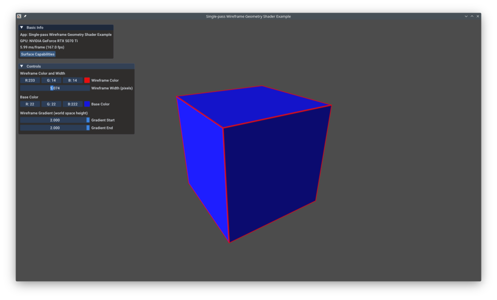
This example shows advanced wireframe rendering that produces smooth, anti-aliased lines of constant pixel width regardless of camera distance. Traditional VK_POLYGON_MODE_LINE produces jagged wireframes and can't overlay on solid fills. This technique uses geometry shaders to compute barycentric coordinates and fragment shaders to calculate distance-to-edge, enabling anti-aliased wireframes with controllable thickness that can overlay solid geometry.
The example uses the KDGpuExample helper API for simplified setup.
Overview
What this example demonstrates:
- Geometry shaders for per-triangle processing
- Barycentric coordinates for edge distance calculation
- Anti-aliased wireframe lines using fwidth()
- Constant pixel-width lines independent of depth
- Wireframe overlay on solid geometry
- Viewport-aware thickness control
Use cases:
- CAD/modeling applications
- Debugging geometry
- Technical visualization
- Stylized rendering (toon shading + wireframe)
- Mesh inspection tools
Vulkan Requirements
- Vulkan Version: 1.0+
- Extensions: None
- Features:
geometryShader(check device support) - Limits: Check
maxGeometryOutputVertices
Key Concepts
Traditional Wireframe Problems:
Using VK_POLYGON_MODE_LINE:
- Lines are jagged (no anti-aliasing)
- Line width in clip space (thicker when closer)
- Can't combine with solid fill in single pass
- Limited line width support (often max 1.0)
Geometry Shader Wireframe:
Solution:
- Render triangles normally (solid fill)
- Geometry shader computes barycentric coords for each vertex
- Fragment shader calculates distance to nearest edge
- If distance < threshold, draw wire color; else solid color
- Use
fwidth()for anti-aliasing
Result: Smooth, anti-aliased wireframes of constant pixel width.
Barycentric Coordinates:
For a triangle with vertices A, B, C, barycentric coords (u, v, w) satisfy:
- Point
P = u*A + v*B + w*C u + v + w = 1- Distance to edge opposite vertex = corresponding coordinate
Example: u = 0 means point is on edge BC.
Geometry shader assigns:
- Vertex 0: (1, 0, 0)
- Vertex 1: (0, 1, 0)
- Vertex 2: (0, 0, 1)
Fragment interpolates these → distance to each edge.
Anti-Aliasing with fwidth():
fwidth(x) returns rate of change of x across pixels:
1 2 3 | |
This creates smooth 1-pixel anti-aliased edges.
Spec: https://registry.khronos.org/OpenGL/specs/gl/GLSLangSpec.4.60.html#built-in-functions (fwidth)
Implementation
Per-Vertex Data:
1 2 3 4 5 | |
Filename: wireframe_geometry/wireframe_geometry.cpp
The excludeEdge flag allows hiding specific edges (e.g., for quad diagonals).
Shader Wireframe Calculation:
1 2 3 4 5 6 7 8 | |
Filename: wireframe_geometry/wireframe_geometry.cpp
Key steps:
- Calculate minimum distance to any edge
- Use
fwidth()for anti-aliasing kernel size smoothstep()creates smooth transition- Mix wireframe and solid colors
Viewport Matrix for Constant Width:
Pass viewport dimensions to maintain constant pixel width regardless of depth. The geometry shader can transform edge distances from clip space to screen space.
Performance Notes
Geometry Shader Cost:
- GPU: Geometry shaders are typically slower than vertex/fragment
- Throughput: Lower than modern mesh shaders
- Mobile: Often unsupported or very slow
Optimization Tips:
- Use only when visual quality justifies cost
- Consider compute-based alternatives for high-performance needs
- On mobile, use
VK_POLYGON_MODE_LINEif acceptable - Batch wireframe draws separately from solid geometry
Alternative Techniques:
- Mesh shaders: Modern replacement for geometry shaders (faster)
- Compute shaders: Generate wireframe geometry on GPU
- Instancing: Draw lines as instanced quads
- Conservative rasterization: Hardware edge detection
See Also
- Hello Sphere Mesh Shader - Mesh shaders (modern alternative)
- Single-Pass Wireframe - NVIDIA technique paper
- Geometry Shaders - OpenGL wiki
Further Reading
- Barycentric Coordinates - Mathematical explanation
- fwidth() Derivatives
- Optimized Wireframe - Fixing NVIDIA Wireframe Shortcomings
Updated on 2026-07-16 at 00:01:15 +0000